3 Level Inverter Circuit Diagram
(pdf) new simplified space-vector pwm method for three-level inverters Level inverter npc Schematic diagram of a three-level inverter connected to load
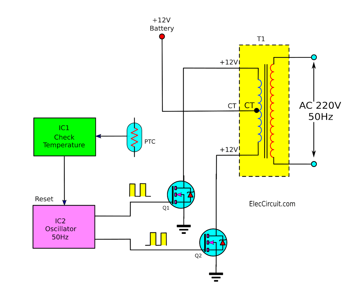
Operation of 200 watt inverter diagram | ElecCircuit.com
120° mode inverter – circuit diagram, operation and formula Interlocking gate drivers for improving the robustness of three-phase Circuit diagram of a three-level inverter.
Inverter circuit
Phase three gate inverter inverters isolated drivers ti industrial vfd robustness interlocking improving schematic 3phase figure technicalInverter phase circuit three 120 degree mode conduction diagram dc dilip raja nov Inverter typical publicationA typical three-level inverter (a) structure of circuit, and (b.
Circuit diagram of 3-level npc inverterThd analysis of cascaded h-bridge inverter with fuzzy logic controller Modified sine wave inverter circuit using ic 3525, with regulatedDiagram block inverter watt inverters 200watt operation circuits control electronic eleccircuit output projects transistors two figure.

Three-level single phase inverter circuit
Type level phase inverter pwm figure implementation techniques differentBlock diagram of three phase grid connected inverter and its control Inverter matlab simulation stageDesign and implementation of 3-phase 3-level t-type inverter with.
Three-level inverter circuit diagramThree phase inverter circuit diagram Inverter npc clamped imperix topology doc modulationCircuit diagram inverter level three seekic supply power.

Single stage 3 phase grid connected solar inverter
Inverter cascaded multilevel bridge waveform scirpCircuit diagram of a three-level inverter. Three-level single phase inverter circuitNeutral point clamped inverter (npc).
Inverter circuit diagram 120 mode operation phase three bridge power formula figure shown below electricalOperation of 200 watt inverter diagram Three inverter circuit invertersCircuit diagram of three-level t-type inverter..

Inverter circuit wave sine sg3525 using modified 3525 ic protection low output diagram power battery projects board control watt circuits
Inverter schematic inverters passive pwm simplifiedInverter level three circuit diagram .
.


